A page for education about the operation of the voltage regulator on a motorcycle
How do you know the difference between the various types of motorcycle regulators/rectifiers?
It is easiest to demonstrate this by simulating the operation of the regulator. We will present several controller modes in a simple web java script simulator. The simulator is interactive and placing the cursor on any element triggers a display of the simulated data associated with it. The pointer above the drawn diagram triggers the lighting of the part of the scheme to which that diagram refers, but this also happens in the opposite situation when the corresponding diagram is illuminated if the pointer is located on the part of the scheme to which the diagram refers. It is also possible to edit and change the scheme in the simulation, as well as save the data to your computer and save the scheme in SVG or png format.
The circuits shown in these simulations are only in principle and are practically difficult to apply. Do not try to do a do-it-yourself project based on these schematics. Many real semiconductors would burn out if used in the manner "simulated" here.
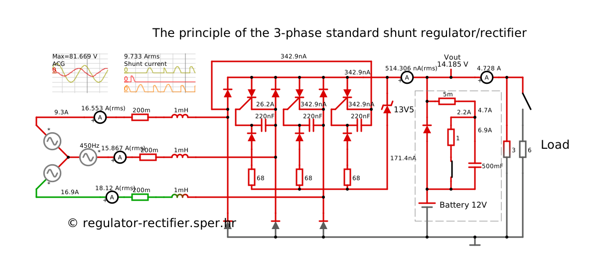
Three-phase standard shunt regulator
With this regulator, after reaching the set voltage, the stator is short-circuited. The current also flows through one of the diodes that rectifies the plus. This type of regulator can also be equipped with thyristors that short circuit to ground. The advantage of this design is that the tripping current branches only to the thyristors that can make a short circuit, and not to all three thyristors. By reducing the load, the short-circuit current increases. That's important to know. Installing headlights that consume less current only increases the short-circuit current. The engine speed can be adjusted in the simulation. Click on the image below to start the simulation in a new tab.
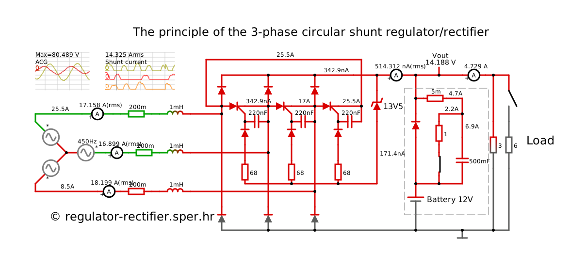
Three-phase circular shunt regulator
With this regulator, after reaching the set voltage, the stator is also short-circuited. The short-circuit current does not flow through the diodes, which is a positive thing about the regulator. The advantage of this design is that the tripping current branches only to the thyristors that can short-circuit, and not to all three thyristors. Decreasing the load also increases the short-circuit current. That's important to know. Installing headlights that consume less current only increases the short-circuit current. The engine speed can be adjusted in the simulation. Click on the image below to start the simulation in a new tab.
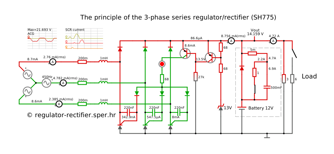
Simple three-phase series regulator (working principle Shindengen SH775)
When Shindengen's regulator SH775 appeared, much was expected, but it turned out that the circuit scheme was not suitable for a three-phase rectifier at high frequencies. This can also be seen on the simulator. When it is set to more than 600Hz, i.e. 6000rpm, the voltage regulation fails and the voltage starts to increase. However, the series type of regulator is an improvement in regulation that results in a reduction of the stator current from the maximum consumption current. Click on the image below to start the simulation.
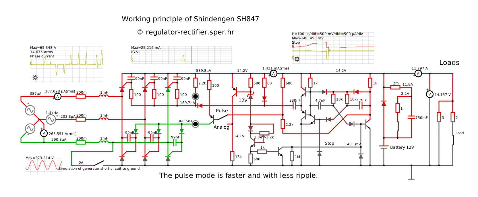
Principle of operation of the three-phase series regulator for high frequencies (Shindengen SH847)
The simulation shown only indicates the possible working principle of the Shindengen SH847 regulator/rectifier. The simulation enables adjustment of the voltage, number of revolutions and capacity of the capacitor between the gate and cathode of the thyristor. It also enables a choice between two operating modes. The current is rectified with 3 thyristors in the plus and three thyristors in the minus. Thyristor triggering in minus is similar to the SH775 simulation, and thyristor triggering in plus is performed by controlling the operation of the oscillator, which pumps current pulses for the gates of the thyristor in plus via the capacitor. The essential thing to control the rectification of a three-phase rectifier in this case is to use 6 thyristors for rectification without diodes. Of course, this circuit has the same problem in practice as a simple series regulator/rectifier: breaking the connection with the battery is most often fatal. The simulation shows how a rectifier of 6 controlled thyristors behaves at a high engine speed. The rectified current pulses are shorter and the voltage control is much better with less ripple than with a simple series regulator. It is important to pay attention that the triggering of the thyristor for plus and minus must overlap in time. Thyristors for the minus cannot be tripped, if the trigger impulse for the plus thyristors does not last during that time. The pulse mode of operation synchronizes this to the maximum, and the analog mode suffers from mismatch and creates more ripple in the output voltage. Click on the image below to start the simulation.
Principle of operation of the three-phase series-
shunt
regulator for high frequencies (3FHVSP)
The presented simulation shows the way in which the series regulator works at a high number of revolutions by activating the circular shut principle, which is the most effective for unblocking the thyristor of the series part of the rectifier. The current level during unblocking is many times lower than the rectified current. Unblocking usually takes a short time, it may be repeated if it was not successful. The regulation circuit of the circular shunt regulator is different in the 3FHVSP regulator because it must be coordinated with the series regulation circuit.
Of course, this simulation only indicates the principle of operation, but not how it looks on our 3FHVSP regulator. In the simulation, it is possible to change the number of revolutions and turn on or off part of the consumer. Click on the image below to start the simulation. For comparison, you can run the simulation of a three-phase circular shunt regulator and see what a big difference it is in the current through the shunt thyristors, especially at high rpm. The characteristics of the AC generator and the load are the same in both simulations. Do not try to make a DIY circuit according to this simulation scheme, because your circuit will probably not work properly and will break soon.
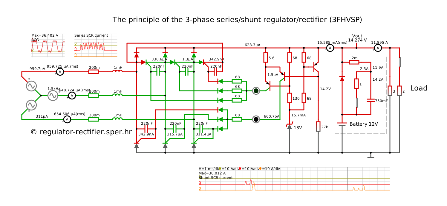
Conclusion of the comparison of the SH847 and 3FHVSP simulations
By comparing these simulations, the conclusion is imposed that the SH847 simulation provides the best voltage regulation with the least stator load. The 3FHVSP regulator only puts a little more load on the stator due to the use of a shunt regulator to turn off the thyristor when the voltage starts to rise uncontrollably at high engine speeds. However, in the real world, the voltage ripple that occurs on the 3FHVSP simulator is not seen at all in the measurements. Everything happens in hundredths of a second. The voltage on the real 3FHVSP regulator is extremely stable. Also, the long-term use of the 3FHVSP regulator did not have a bad effect on the battery's durability. The reason is probably that lead-acid batteries are fed some AC current (principle of desulphation), but since the voltage regulation is precise, the AC current to the battery does not have a large amplitude that would harm the durability of the battery. We even have experiences of users of the earlier version of the 3FHVSP regulator, where the battery used to last for 7 seasons.
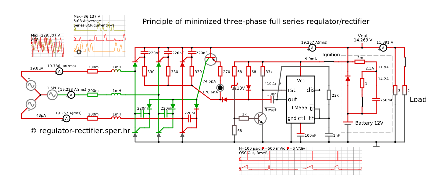
Principle of a minimal three-phase fully series regulator/rectifier with ignition
This schematic diagram is a minimized circuit with an identical operating principle to the SH847 simulation. The thyristor triggering for plus and minus is perfectly synchronized and works at high frequencies without problems. The oscillator used is an LM555, which is controlled by a voltage comparator. The LM555 is also an oscillator and a driver for trigger pulses via a 330nF capacitor. The simulation has the ability to change the engine speed. Voltage measurements are made via the Ignition+ input.
However, in reality, the LM555 works up to a maximum of 16V. So, although the circuit is almost suitable for the project itself, it is dangerously sensitive to increased battery voltage. The solution is to replace the LM555 with the UC3845, which has a comparator, oscillator and pulse driver on it, and can withstand voltages up to 30VDC. Start the simulation by clicking on the image below.
-
Home -
Regulators- All types of regulators
- 3FHVSP regulator/rectifier
- Quality
- List of replacement regulators
- Ordering
- Price list
- Aprilia Caponord ETV1000
- Aprilia Tuono 1000
- BMW F650
- Honda CBR 600 600F 900 1000 1100
- Hyosung GV250 GT250 GV650
- Kawasaki KLE500
- Piaggio Beverly 250 400 500
- Polaris Sportsman 570 850 1000
- Suzuki GSXR 600 750 1000
- Tomos 4.8 10 18
- Yamaha YZFR1 YZFR6
-
Publication-
Articles
- History of the 3FHVSP regulator/rectifier
- Replacement for Shindengen SH847
- Advantages of the series type regulator
- Project DIY best series regulator
- Battery voltage charging control
- What to do when the regulator/rectifier overcharges?
- What to do when the regulator often burns out?
- What to do when the stator often burns out?
-
Documentation
- List of regulators
- Price list of regulators
- Troubleshooting
- Guide for Quick Solution of Voltage Drop
- Comparison of SER/PAR Regulators
- Animation of SER/PAR Regulator
- 14V-3FHVSP-30A-AX/BX-KS-LI
- DP14V-3FHVSP-30A-AX/BX-KS-LI
- 14V-3FHVSP-30A-AX/BX-K2-LI
- 14V-3FHV-30A-A/B-LI
- 14V-3FHV-30A-A/B-LO
- 14V-3FHV-30A-A/B-T-LI
- 14V-3F-15A-A/B-LI
- 14V-1F-10A-A/B-LI
- DP14V-1F-10A-A/B-LI
- 14V-1F-15A-A/B-K-LI
- 14V-1F-20A-A/B-LI
- 14V-1F-20A-A/B-LO
- 14V-1F-20A-A/B-K-LI
- 14V-1F-20A-A/B-K-LO+
- 14V-1FHV-10A-A/B-LI
- 14V-1FHV-30A-A/B-LI
- DP14V-1FHV-30A-A/B-LI
- 14V-1FHV-30A-A/B-LO
- 14V-1FHV-30A-A/B-K-LO
- 14V-1FHV-30A-A/B-K-LO+
- 14V-1FHV-30A-A/B-T-LI
- 14V-1+1FHV-30A-A/B-LI
- 14V-1+1FHV-30A-A/B-LO
- HVSP flyer
- Prospekt reglera (croatian)
- Housing diagrams
- Education
- News
-
Articles
-
Troubleshooting -
Contact -
More -
Hrvatski